Thickness Gauges
TGS-9000

|
|
Introduction - The E.S.C.
Resources TGS-9000 non-contact thickness gauges provide fast and reliable on line thickness
measurements and SPC reporting for strip and sheet material. The direct
benefits provided by this measurement are documented compliance with
quality specifications, improved process control and a reduction in scrap.
The standard system provides disk storage for the SPC information to
eliminate the need to maintain large files of printer paper for long term
record keeping purposes.
Principal of Operation - This
gauge uses the scientific principle that matter will absorb a low
power radiation beam in proportion to it's composition and thickness. As
the material passes between the X-Ray source and detector, variations in
thickness cause measurable variations in the amount of x-ray reaching
the detector head. The gauge is calibrated based on these variations,
and provides a continuous, high speed, non-contact, accurate and reliable
measurement of thickness.
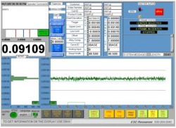
System Display - in it's normal
mode of operation, the 17" full color monitor displays actual
thickness, deviation, upper and lower tolerance limits, shutter status,
coil footage, and a graphic display of thickness for the complete coil.
The thickness display changes from green to red if the thickness goes
out of tolerance. Additional display screens are provided for operator
setup, I/O status, and trouble shooting diagnostics.
 |
System
Display
Click on the image to the left for a larger view. |
.

Features
 | Easy Installation - no
requirements for air or water. "C" frames typically mount
on two pedestals and require a minimum of cabling. |
 | Accuracy - state of the art
high speed electronics and logarithmic linearization performed by
the software assures highly accurate measurements of various
materials while minimizing the hardware requirements. A 4" ion
chamber is used in the detector head, resulting in a surface area
77% greater than the gauges with 3" chambers. This translates
to more accurate and stable thickness measurements. |
 | Reliability - this system uses
a modern personal computer, providing a software based system that
reduces the requirement for peripheral hardware. This arrangement
provides a very reliable "platform" for thickness
measurement and SPC reporting. |
 | I/O Capabilities - hardware is
provided to enable communication with a host computer or process
control unit. |
 | Automatic Standardization - this provides a fast, accurate
standardization cycle. Up to 10 calibration curves are available to
permit measurement of a wide variety of material types. |
 | Diagnostics - system faults
are stored and displayed on demand. A description of the fault and
possible corrective action is also displayed. |
 | Upgradeable - this system is
software based, which enables future upgrades to be performed in the
field, via software changes by the customer. |
 | Dual Beam Systems - enable the
measurement of a wider variety of products. |
 | Automatic Alloy Compensation -
the system automatically calculates the curve compensation for
different alloys. |
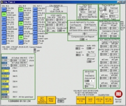 |
Engineering
Set-Up Page
This page is used to customize the system and
to test all inputs and outputs.
Click on the image to the left for a larger view.
|
|
|
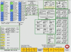 |
Engineering
Test Page
Oscilloscope display can be used to monitor analog inputs and detector head input.
Click on the image to the left for a larger view.
|
|
|
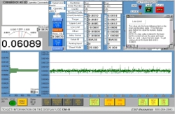 |
Dynamic
On-Line Help
On Line Help Pop-up windows provides information on function
or parameter.
Click on the image to the left for a larger view.
|

SPC Reports
 | Thickness Deviation Plot -
presents a graphic representation of strip thickness over the coil
length, in a strip chart fashion. Also indicates location of out of
tolerance material. |
 | Coil Report - presents a
histogram of thickness distribution, footage, average thickness, UCL,
LCL, X Double Bar, R Bar and CPK. Up to three different reports can
be developed for each coil. |
 | Shift Summary Report - presents a shift summary of
production. |
Note: No optional equipment is
required for disk storage of the Coil Report and the Shift Summary
Report. In addition, both of these reports are customer formattable on
site.
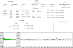 |
Coil
Report
Click on the image to the left for a larger view.
|

Options
 | Manual "C" Frame -
operator manually positions "C" frame on sheet. |
 | Electric "C" Frame -
an electric drive motor allows the operator to position the
"C" frame from the operator's station. |
 | Scanning "C" Frame -
an electric drive configuration equipped with additional logic and
control circuits to enable the gauge to automatically scan from one
edge of the strip to the other. |
 | Other Options - other options
are available depending on your specific needs. |

Specifications
|
Range: |
Steel: 0.000 - 0.250" |
|
|
Copper, Brass & Nickel: 0.000 - 0.200" |
|
|
Aluminum: 0.000 - 0.500" |
|
Air Gap: |
2 - 8" (6" normal) |
|
Response Time: |
10 - 999 milliseconds (software selectable) |
|
Calibration Accuracy: |
+/- 0.20% or 90u"(2.3um) over 0 - 0.200" |
|
Radiation Source: |
Am241: 1 or 2 Curies |
|
|
Sr90: 100 mCi |
|
Radiation Detector: |
Ion Chamber: 4" diameter - 4 ATM |

Thickness Gauge Brochure
Download a Printable Thickness Gauge
Brochure
in Adobe Acrobat PDF Format:
Thickness Gauge Brochure: TG-9000
You must have Adobe Acrobat Reader 3.0
to view and print the Registration Form.
Click on the logo below to link to their website and download Acrobat
Reader free.

Information Request Form
To request additional information on the
E.S.C. Resources TGS-9000 Thickness Gauge please click here: Information
Request Form.

   |
|